NDS.Live defines a compact, integer-based scheme for representing geographic positions and for dividing the surface of the Earth into addressable tiles. This page reproduces the normative specification for coordinate encoding and the packed tile ID, and links open-source reference implementations at the end.
Coordinate encoding
NDS.Live uses WGS 84, the World Geodetic System dating from 1984, as the standard coordinate reference system for representing the latitude and longitude of objects. WGS 84 defines a fixed global reference frame for the whole Earth for use in geodesy and navigation. By using this standard coordinate reference system, it is possible to uniquely identify any point on the Earth's surface (except the North Pole) by two numbers, the x-coordinate and the y-coordinate of the point, where x corresponds to the longitude and y to the latitude.
For coding coordinates, a scaling factor is applied so that 360° correspond to 232, to exhaust the full range of 32-bit signed integers. In NDS, a coordinate unit corresponds to 90 / 230 degrees of longitude or latitude. Longitudes range between −180° and +180° and latitudes between −90° and +90°. Hence, coordinate values are in the range of −231 ≤ x < 231 for longitudes and −230 ≤ y < 230 for latitudes. This means that for latitudes, 31 bits are sufficient.
y = floor( latitude° × 230 / 90 ) // −230 ≤ y < 230
The intention of this encoding is to represent the x-coordinate as signed 32-bit integers, x = x31 x30 … x1 x0, and the y-coordinate as signed 31-bit integers, y = y30 y29 … y1 y0, where x31 and y30 are the most significant bits and x0 and y0 are the least significant bits. The origin of the coordinate system is the intersection of the WGS 84 zero-meridian and the equator.
Integer coding of WGS 84 coordinates
To convert WGS 84 coordinates given as floating-point values into integer values, the following operations are available:
- Floor operation: rounds down to the next integer.
- Truncate operation: always rounds toward zero. That is, it rounds down to the next integer for positive values and it rounds up to the next integer for negative values.
- Round operation: rounds up or down toward the nearest integer.
It is recommended to use the floor operation because it always rounds in the same direction. This results in a better consistency with the tiling scheme.
NDS uses the two's complement format. This allows for the derivation of values of
the 31-bit y-coordinates by using ordinary 32-bit integers and masking off the most significant bit.
For example, the value −273788154 equals the hexadecimal value
6fae5306 as a 31-bit integer and
efae5306 as a 32-bit integer, due to sign-bit extension.
Morton code
The Morton code can be derived from a coordinate that is defined by two integer values for longitude (x) and latitude (y). The Morton code is a single number; that is, two dimensions are mapped into one dimension. For a given coordinate with x = x31 x30 … x1 x0 and y = y30 y29 … y1 y0, the Morton code c is given by the 63-bit integer that results from interleaving the bits of the x- and y-coordinate:
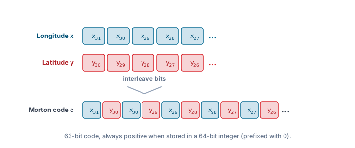
If the Morton code c is stored in a 64-bit integer, it is always positive because it is prefixed with a 0-bit. If items are ordered according to their Morton code, then we speak of a Morton order.
Tiles
Like most map formats, NDS.Live organizes geographic data into tiles, bounded pieces of the Earth's surface that can be requested and cached independently. A tile contains all the data that logically or geographically belongs to it, and is referenced by a single numeric tile ID.
What makes this work is that the grid is fixed and shared by every map: the tile that contains a given position can be computed directly from its coordinates in constant time (O(1)), with no spatial index, search, or lookup table. Every tile also has a compact numeric identifier, its packed tile ID, derived directly from the coordinate encoding above. The rest of this page describes the tiling scheme and how the tile ID is built.
Tiling scheme
NDS.Live uses a global fixed tiling scheme. The scheme forms a uniform grid that divides the entire surface of the Earth into tiles. The tiles form approximately rectangular territorial sections. NDS defines a tile as follows: if (x1, y1) is the southwest corner of a tile and (x2, y2) is its northeast corner, then all positions (x, y) with x1 ≤ x < x2 and y1 ≤ y < y2 are uniquely assigned to the tile.
The tiling scheme uses multiple levels. For each level, the union of the maximum number of tiles available on that level covers the entire surface of the Earth. All tiles on the same level are bounded by tile borders of constant latitude and constant longitude. That is, the size of the tiles on one level is always equal in terms of coordinate units (fixed tiling scheme).
Tile levels
The highest level of the NDS.Live tiling scheme has two tiles. On the next lower level, each of these tiles is split into four with equal extent in each direction. This is continued through all levels down to the lowest level, thus forming a hierarchical structure from global into detail. Each level has its own underlying tiling structure, and higher-level tiles are represented as the union of lower-level tiles.
The highest or least-detailed level in NDS.Live is labeled level 0. The lowest or most-detailed level is labeled level 15. Not all levels need to be available in an NDS.Live map. NDS.Live services that use tiles indicate the supported tile levels.
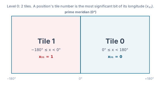
On level 0, whether a location on Earth belongs to tile 0 or tile 1 is determined by the most significant bit of its longitude in coordinate units (x31). For tile 0, this means longitudes in the range of 0° ≤ x < 180°, and for tile 1 longitudes in the range of 180° ≤ x < 360° (signed: −180° ≤ x < 0°). Thus, for all coordinates contained in a level 0 tile, the tile number is identical to the value of the most significant bit of their Morton code.
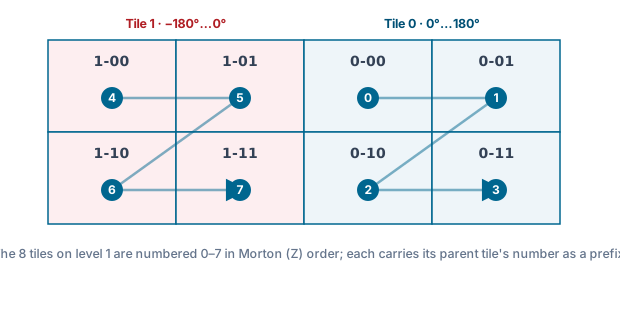
On level 1, the tile numbers are identical to the three most significant bits of the coordinates' Morton codes. As indicated by the dash in the tile labels, each tile number also contains the tile number of its parent tile as a prefix. On level 2 and below, tile numbering continues according to the same Morton scheme.
Tile matrix
A tile is a matrix consisting of cells (discrete locations), which are identified by row and column. The number of rows and columns is equal. All tiles on the same level have the same number of cells. The number of cells per row or per column is 231−k, where k is the level number.
The addressable number of cells per tile depends on coordinate width. In terms of coordinate units, the side length of a level-k tile is 231−k. The level-k tiling has 22k+1 tiles. The tile number of a level-k tile is given by the most significant 2k+1 bits of the Morton codes of the coordinates covered by that tile.
The last column of the 180° meridian is empty. Because of the NDS encoding, it is not possible to calculate an absolute value based on the last column of the 180° meridian.
The tile anchor point is defined as the number of rows divided by two and the number of columns divided by two.
Tile identifier: the packed tile ID
Tiles are identified via their packed tile ID. Each packed tile ID consists of the level number followed by the tile number; the physical encoding packs both components into one 32-bit value.
The number of tiles on level 0 is two and increases by a factor of four with each level. This is why the tile number can be encoded by one bit on level 0 and additional two bits for each lower level. For example, three bits are needed on level 1 and 31 bits are needed on level 15 for encoding the tile number. The remaining bits are used to encode the level number. Encoding the level is necessary because the ranges of tile numbers overlap between levels.
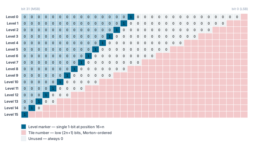
Tile numbers are created according to Morton order. The tile number on level 0 consists of one bit, which is set according to the most significant bit of the longitude of the southwest corner of a tile. For each lower level, the tile number is extended by two bits. The tile number is built from the bit(s) of the parent tile number and the nth bit of the latitude and longitude of the southwest corner of the tile, where n is the level number and bits are counted from the most significant as bit 0. That is, the tile number is identical to the (2n+1) most significant bits of the Morton code of the southwest corner of the tile.
To generate a packed tile ID, the tile number and level number are combined. The referenced level number n is encoded as 216+n; for example, 65536 = 216 for level 0. After encoding, a bitwise OR operation is used to generate the packed tile ID.
int32. This surprises people the first
time they see it; it is a long-standing choice rooted in languages without unsigned integer types
(notably Java). Treat the tile ID as a raw 32-bit pattern rather than a signed magnitude. The
ndslive-math reference implementations handle this for you.
Reference code
The ndslive-math repository provides open-source reference implementations of everything on this page: NDS ↔ WGS 84 coordinate handling and conversion, NDS packed tile IDs, and Morton code (Z-order curve) encoding and decoding, in C++, Python, Java, JavaScript/TypeScript, Go and Rust.
ndsev/ndslive-math
Coordinate conversion, packed tile IDs and Morton codes, in six languages. Open source.
Looking for the complete NDS.Live format: modules, smart layers, services and tooling? Head to the Developer Portal →